Do you want to set up lighting to turn on at a specific time? Organize automatic watering of your garden beds throughout the day? If you have a house and need to turn on a pump for a duration sufficient to fill a tank with water? For these and many other household tasks related to turning electrical devices on and off at scheduled times, time relays are used.
And if you work in industry, you know how widely time relays are used in process automation systems.
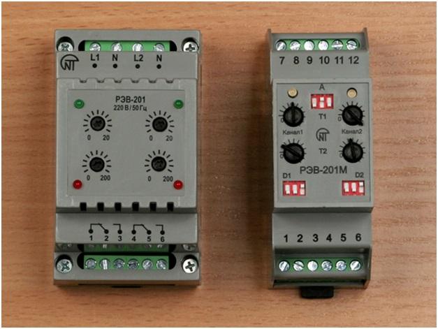
Among modern time relays, the REV-201 and REV-201m models from “Novatek-Electro” are worth noting.
These are dual-channel electronic devices designed for switching electrical processes of alternating and direct current with adjustable short delays.
Time Relays in Automation
_______
Time relays have been traditionally used in automation schemes for many decades. Even modern programmable logic controllers, which incorporate time relay functions in software, have not been able to replace these devices. For simple tasks, time relays remain unmatched due to their ease of use and low cost.
In industry, time relays are traditionally used either as part of complex automation systems or separately to control simple objects: pumps, drives, etc. The REV-201m model, among other things, can be used as a pre-start alarm relay for equipment governed by the State Mining Supervision Department's Regulation No. 47 of 04.06.03, including for mining and beneficiation plants.
In agriculture, time relays are used in drip irrigation systems, feed delivery, and more.
In the electrical systems of enterprises, time relays are used in lighting circuits to turn them on at specified times. This is especially relevant due to the rising cost of electricity.
Finally, time relays have a vast range of applications in everyday life, especially in country houses and dachas. They can control heater activation at set times, manage drip irrigation, control outdoor lighting, and more.
For instance, here's how one country house resident used a time relay. The house does not have central water supply, but there is a well nearby. Fetching water with buckets from the well is not appealing—it's the 21st century. The homeowner placed a submersible pump in the well, which, when turned on by the time relay, runs for an hour, sufficient to fill a large tank (the time was adjusted experimentally), and then turns off. This is an example of the time relay working with a “delay off” algorithm. The water is then used in the house for domestic needs, and when it runs out, the homeowner turns the pump on again.
Of course, an experienced automation engineer would solve this problem more precisely according to automation system standards. For instance, they would add sensors for the upper and lower levels of the water tank. However, the implemented project is excellent precisely because of its simplicity, affordability, and accessibility to an ordinary person. And even if the pump is turned on before the tank is fully emptied, excess water will simply drain through the overflow outlet at the top.
Modernization of Old Automation Systems
_______
Time relays have been used in automation systems for many decades. They have been known since at least the 1930s. Many enterprises still use time relays from the 1980s and even the 1970s. Many of them are now quite worn out and need replacement. They can be replaced with modern time relays like the REV-201 or REV-201m models. This way, the automation system does not need to be changed. Additionally, these devices have a number of advantages.
Modern models, while functionally similar to their predecessors from the 1970s and 1980s, are structurally quite different due to the use of microcontrollers and new electronic components.
For example, let’s compare the time relay RV 127 UHL4 from 1985 and the modern REV-201 device.
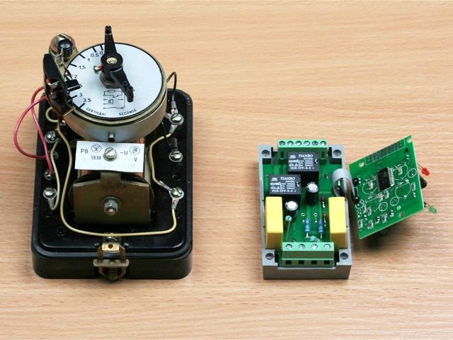
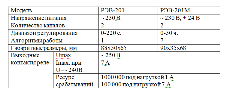
Functionally, the devices are similar; both are used for switching electrical processes with a delay in activation. However, the REV-201 has a larger adjustment range: 0-220 seconds, compared to 0-3.5 seconds in the RV 127 UHL4. Additionally, the REV-201 has two independent control channels, while the RV 127 UHL4 has only one.
Structurally, the devices are completely different.
The Soviet device uses a mechanical clock mechanism for timing, while the modern REV-201 uses a microcontroller for this function. Consequently, the timing accuracy and reliability of the modern device are superior.
The switching capacity of the output contacts in the REV-201 is also higher: 1,000,000 cycles at 1 A (100,000 at 5 A) compared to just 5,000 in the Soviet model.
Construction
_______
The REV-201 and REV-201m time relays are housed in enclosures designed for mounting on DIN rails. The front panel includes connection terminals, indicators, and control elements.
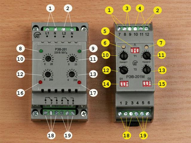
- Power supply ~ 230 V for channel 1
- Power supply ~ 230 V for channel 2
- Power supply ± 24 V for channel 1
- Power supply ± 24 V for channel 2
- Switching contacts for both channels
Below are the control elements on the front panel:
- LED indicators: for the status of each channel.
- Switches: for selecting the operating mode of each channel.
- Adjusting knob: for setting the time delay.
Technical Data
_______
Power supply
- Channel 1: ~230 V or ±24 V
- Channel 2: ~230 V or ±24 V
Delay range: 0-220 seconds
Output contacts: 1,000,000 cycles at 1 A, 100,000 cycles at 5 A
Mounting: DIN rail
Enclosure: Plastic, IP40
Dimensions: 90 x 90 x 60 mm


